Basic Logic Gates
The Digital Logic Gate is the basic building block from which all digital electronic circuits and microprocessor based systems are constructed from. They perform logical operations on binary numbers. In digital logic world only two states are allowed. Those are boolean "1" and "0" or logic state "HIGH" and "LOW" or "TRUE" and "FALSE" or most of the time 5V/3.3V/1.8V and 0V. Almost all electronic devices we use today will have some form of logic gates in them.
There are seven types of basic logic gates:
| Gate | Symbol | Description |
|---|---|---|
| NOT | 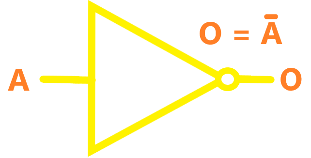 |
A logical inverter, sometimes called a NOT gate to differentiate it from other types of electronic inverter devices, has only one input. It reverses the logic state. If the input is 1, then the output is 0. If the input is 0, then the output is 1. |
| AND | 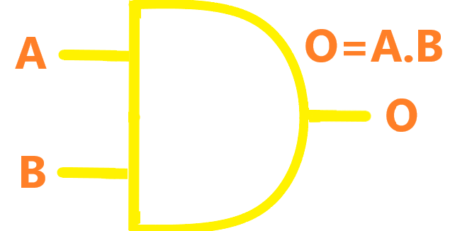 |
The AND gate acts in the same way as the logical "and" operator. The output is "true" when both inputs are "true". Otherwise, the output is "false." In other words, the output is 1 only when both inputs one AND two are 1. |
| NAND | 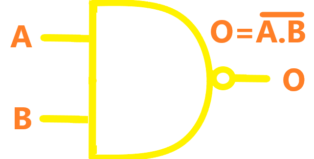 |
The NAND gate operates as an AND gate followed by a NOT gate. It acts in the manner of the logical operation "and" followed by negation. The output is "false" if both inputs are "true". Otherwise, the output is "true". |
| OR | 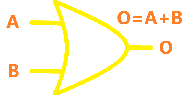 |
The output of OR gate is "true" if either or both of the inputs are "true". If both inputs are "false", then the output is "false". In other words, for the output to be 1, at least input one OR two must be 1. |
| NOR | 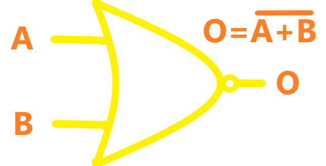 |
The NOR gate is a combination OR gate followed by an inverter (NOT gate). Its output is "true" if both inputs are "false". Otherwise, the output is "false". |
| XOR |  |
The output of XOR gate is "false" if both inputs are "false" or if both inputs are "true". Another way of looking at this circuit is to observe that the output is 1 if the inputs are different, but 0 if the inputs are the same. |
| XNOR | 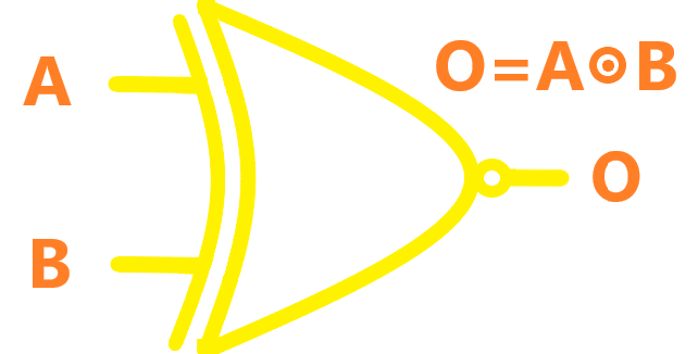 |
The XNOR (exclusive-NOR) gate is a combination XOR gate followed by an inverter (NOT gate). Its output is "true" if the inputs are the same, and "false" if the inputs are different. |